Couplings
Spacer 100
PHE SM25-100DBSE
Spacer 100
PHE SM25-100DBSE


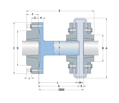
| Distance Between Shaft Ends (DBSE) Nominal | 100 |
| Distance Between Shaft Ends (DBSE) Nominal (in) | 3.94 |
| Distance Between Shaft Ends (DBSE) Max | 114 |
| Distance Between Shaft Ends (DBSE) Max (in) | 4.49 |
| Coupling size | 70 |
| Spacer Bush Size | 2517 |
| Bore Min (mm) | 16 |
| Bore Min (in) | 0.63 |
| Bore Max (mm) | 60 |
| Bore Max (in) | 2.36 |
| Coupling Bush Size | 2012 |
| Bore Min (mm) | 14 |
| Bore Min (in) | 0.55 |
| Bore Max (mm) | 50 |
| Bore Max (in) | 1.97 |
| A | 187 |
| A (in) | 7.36 |
| B | 80 |
| B (in) | 3.15 |
| C | 178 |
| C (in) | 7.01 |
| D | 123 |
| D (in) | 4.84 |
| E | 180 |
| E (in) | - |
| F | 45 |
| F (in) | 1.77 |
| G | 22 |
| G (in) | 0.87 |
| H | 16 |
| H (in) | 0.63 |
| J | 14 |
| J (in) | 0.55 |
| K | 9 |
| K (in) | 0.35 |
| L | 80 |
| L (in) | 3.15 |
| M | 23 |
| M (in) | 0.91 |
| S | 94 |
| S (in) | 3.7 |
| T | 48 |
| T (in) | 1.89 |
Please note:
An SKF Flex coupling consists of 2 flanges and 1 tyre.
An SKF Flex spacer coupling consists of 2 flanges, 1 tyre and 1 spacer (spacer part number consists of spacer shaft and rigid flange).
An SKF Flex coupling consists of 2 flanges and 1 tyre.
An SKF Flex spacer coupling consists of 2 flanges, 1 tyre and 1 spacer (spacer part number consists of spacer shaft and rigid flange).